Programming a PIC on Linux Tutorial
I've done several hobby projects involving a PIC and after figuring out some tips and tricks of doing this completely with Linux I figured I'd write a complete tutorial on how to get started. PICs are extremely cheap, easy to use, and with the variety and features available the possibilities are endless.
For this tutorial I'm going to use the 8-bit PIC16F688 (PDIP-14). You're going to want to download the datasheet for whatever PIC you have and adjust as necessary if you don't use the same PIC.
To start, you will need a PIC programmer. The one I use most often is the cheap and reliable ICA01 - USB PIC PROGRAMMER SET. While I have the set, I rarely use the adapter. I almost always just program the chips inline in the circuit right on the breadboard. You can decide if you want to save a few bucks or not.
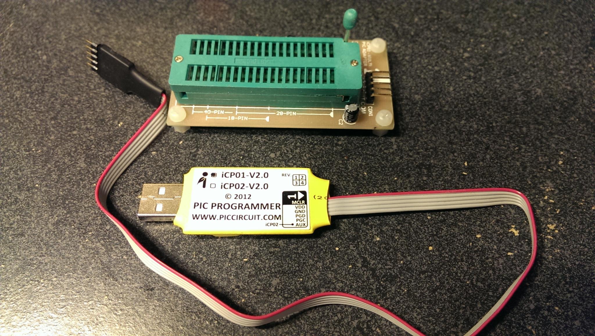
To use the programmer, you'll need to download and install Microchips PICkit 2 Command Line Interface. This gives you the pk2cmd that allows you program the hex file to the PIC that we'll generate later with the compiler.
You can find the source code on Microchip's unsupported source code site. Download it, extract it, compile it, and install it. You may have to install libusb-dev first.
sudo apt-get install libusb-dev
Then extract, build, and install.
$ tar xf pk2cmdv1.20LinuxMacSource.tar.gz
$ cd pk2cmdv1.20LinuxMacSource
$ make
$ sudo make install
This installs 2 files: /usr/local/bin/pk2cmd and /usr/share/pk2/PK2DeviceFile.dat
You can plug in your USB programmer and run the following command to make sure your programmer is detected:
$ pk2cmd -S

Unit #     Unit ID
0          iCP01-V2.0

Operation Succeeded
Next, you need the actual compiler. Small Device C Compiler is the compiler of choice. There's already an Ubuntu package for it to take care of installing it.
sudo apt-get install sdcc
Now, we need to setup our test circuit. The first thing we have to do is look at the iCP01 manual to see the pinout of the ICSP connector.
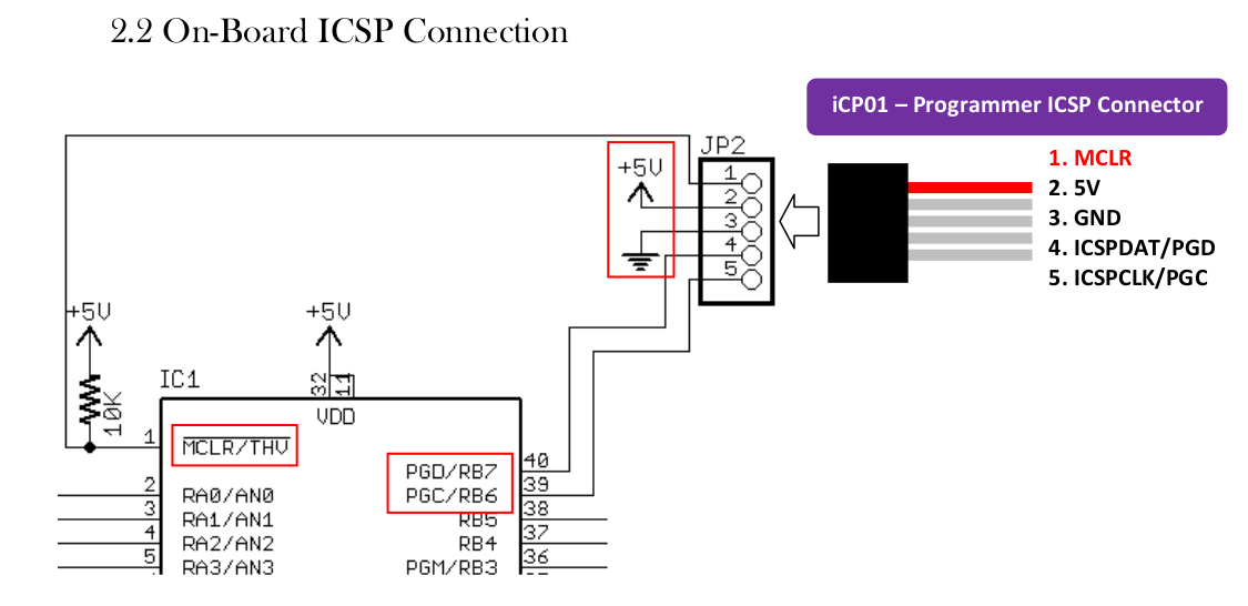
Then, we need to find the pinout of the PIC from the datasheet.
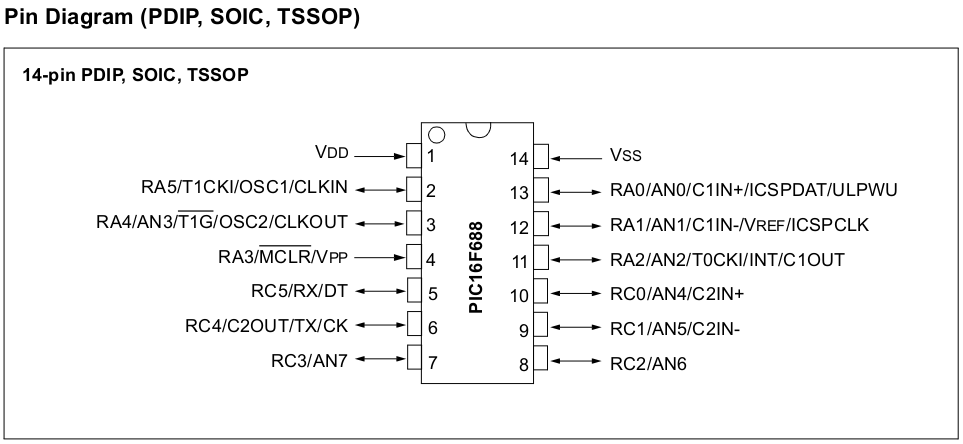
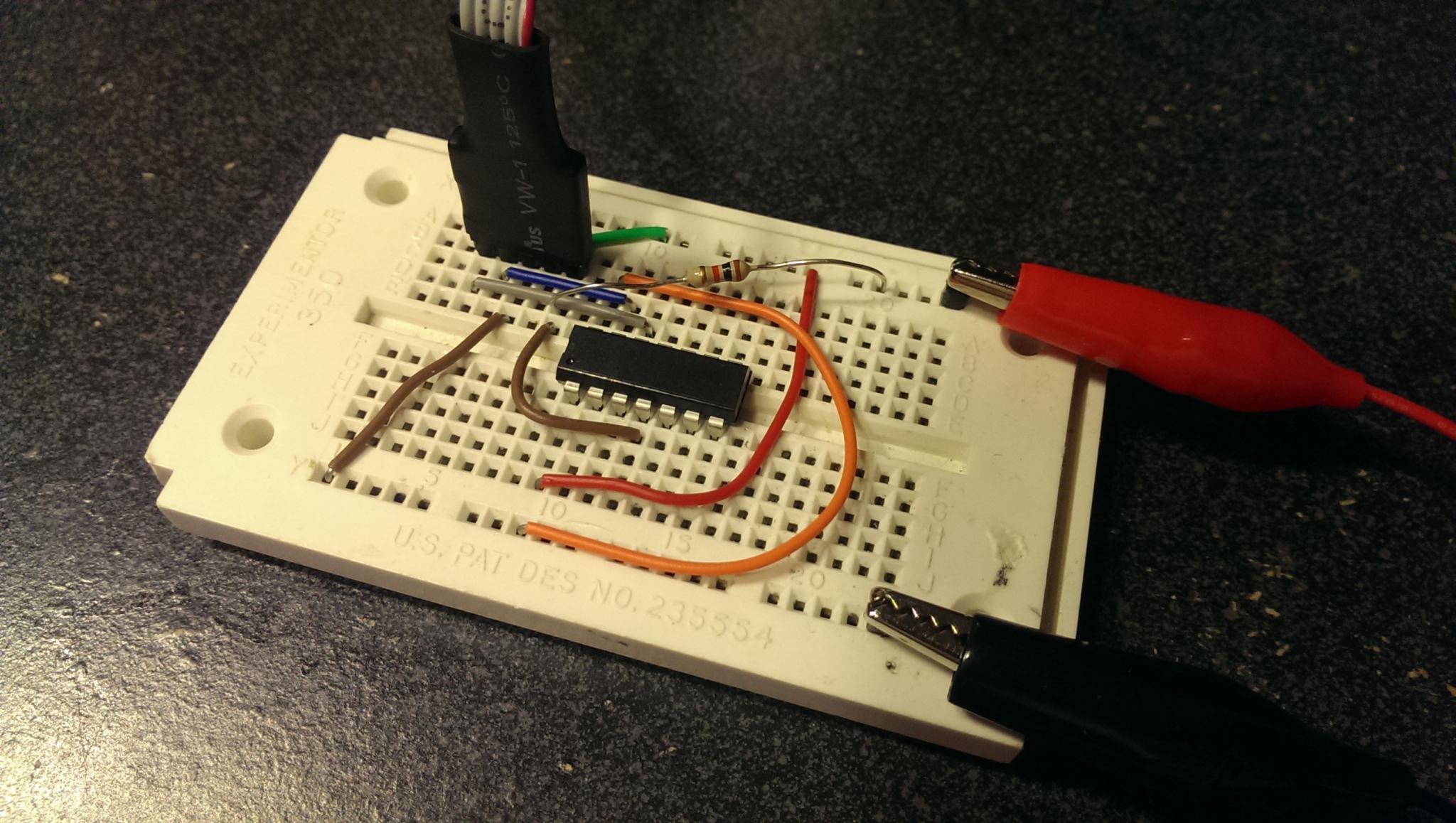
Mapping those two together, the following circuit is needed to connect the programmer to the PIC inline. The ICSP header is connected up to the PIC with an additional 10K pullup resister connecting the MCLR to Vdd. The red probe is the positive from the power supply and the black is the negative.
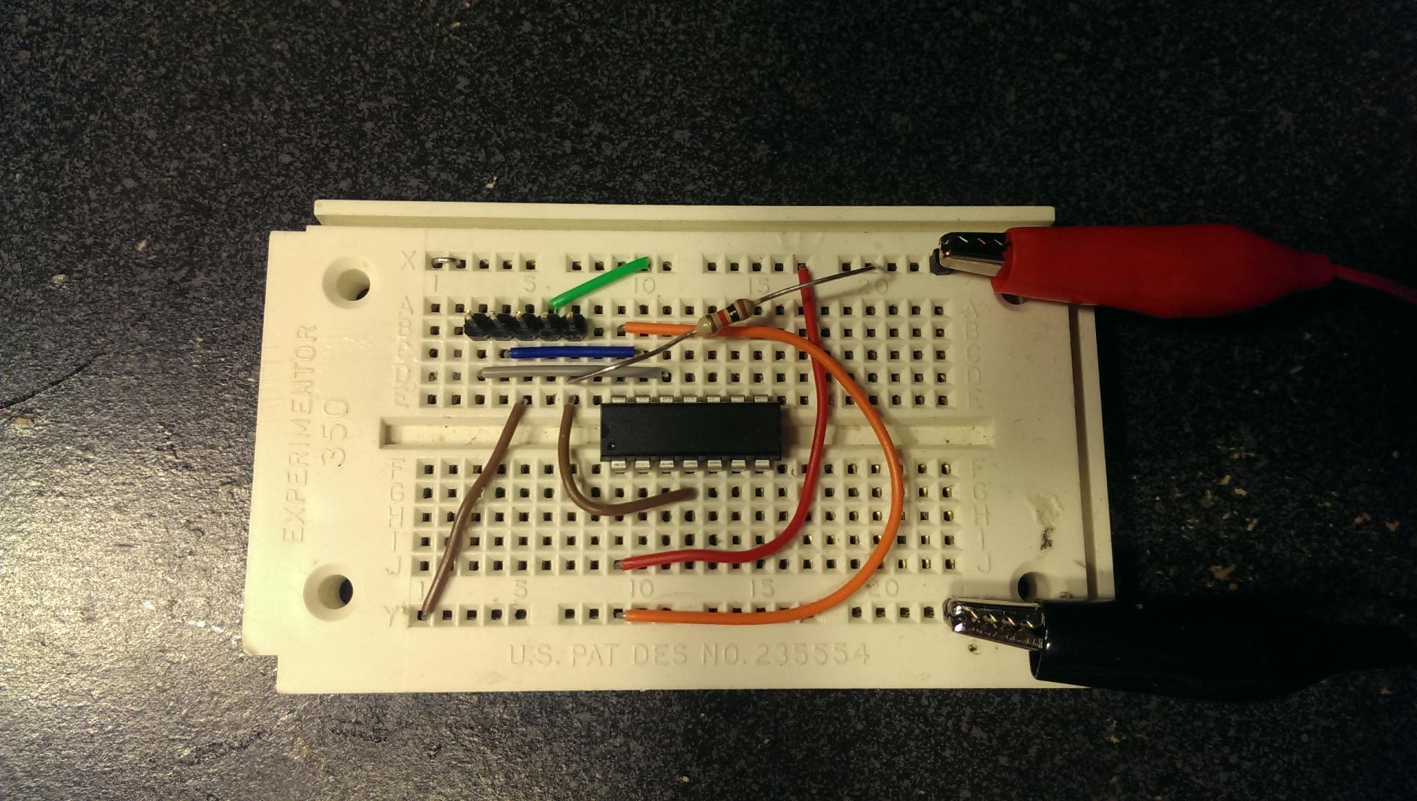
Here it is with the programmer connected to the header.
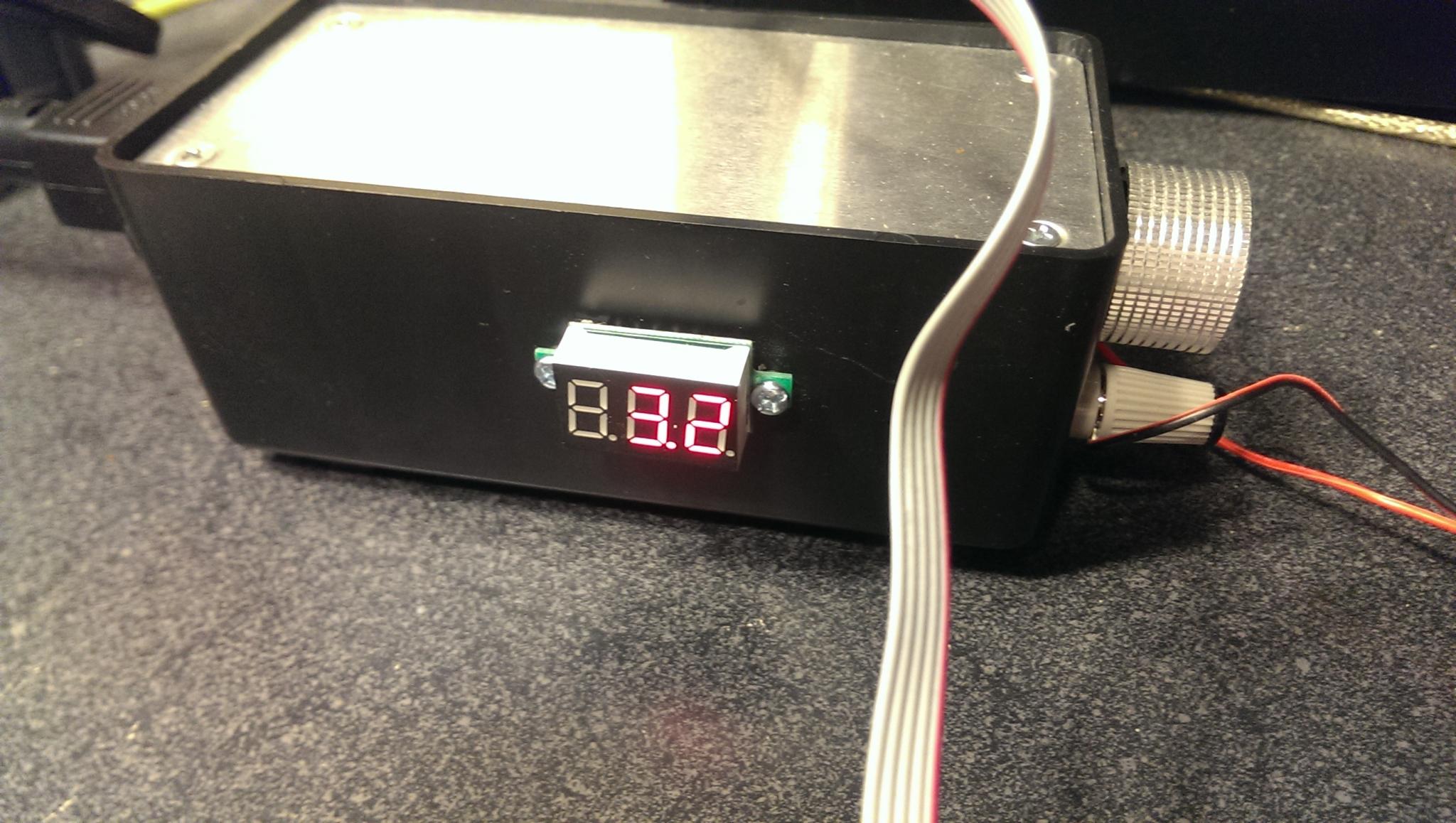
I am using a DC power supply at 3.2 volts that I built in a previous blog entry.
This is the makefile I use. It has a default target to not only build the main.hex file, but also has a program target to actually program the PIC.
all: main

main: main.c
	sdcc -mpic14 -p16f688 main.c

program:
	pk2cmd -B/usr/share/pk2/ -PPIC16F688 -Fmain.hex -M -R
The -R option is a flag to tell the programmer to release the MCLR immediately after it finishes. This starts the program running. You can run pk2cmd without any parameters to see what options are available.
Now for the example program. It simply turns RC3 pin on and off every 500 milliseconds. There's not much to it, but there are a couple of things to note. The config is an expected symbol that sdcc looks for to set the configuration for the PIC. You'll have to set this up appropriately. The datasheet explains what all of these mean and the header file for the PIC has all of the available options already defined for you. You can find the pic16f688.h header file in /usr/share/sdcc/include/pic/ which has all of the defines you'll need to use the PIC. Most of the match up naming wise directly to the datasheet.
#include <pic/pic16f688.h>

typedef unsigned int config;
config at 0x2007 __CONFIG = _CPD_OFF &
   _CP_OFF &
   _PWRTE_OFF &
   _WDT_OFF; // watchdog off

/* Using Internal Clock of 8 Mhz */
#define FOSC 2000000L

#define delay_us(x) {  unsigned char us;	\
      us = (x)/(12000000/FOSC)|1;		\
      while(--us != 0) continue; }

void delay_ms(unsigned int ms)
{
   unsigned char i;
   do {
      i = 4;
      do {
	 delay_us(164);
      } while(--i);
   } while(--ms);
}

void main()
{
   ANSEL = 0b00000000; // disable analog inputs
   CMCON0 = 0x07 ; // disable comparators
   TRISA = 0b00001100; // PORTA all outputs, except RA3 and RA2
   TRISC = 0b00000000; // PORTC all outputs

   PORTA = 0b00000000; // start with everything Low
   PORTC = 0b00000000; // start with everything Low

   while (1)
   {
      RC3 = 1;
      delay_ms(500);
      RC3 = 0;
      delay_ms(500);
   }
}
Now we can compile the program.
$ make
sdcc -mpic14 -p16f688 main.c
message: using default linker script "/usr/share/gputils/lkr/16f688.lkr"
Then, program it:
$ make program
pk2cmd -B/usr/share/pk2/ -PPIC16F688 -Fmain.hex -M
PICkit 2 Program Report
7-3-2014, 19:44:03
Device Type: PIC16F688

Program Succeeded.

Operation Succeeded
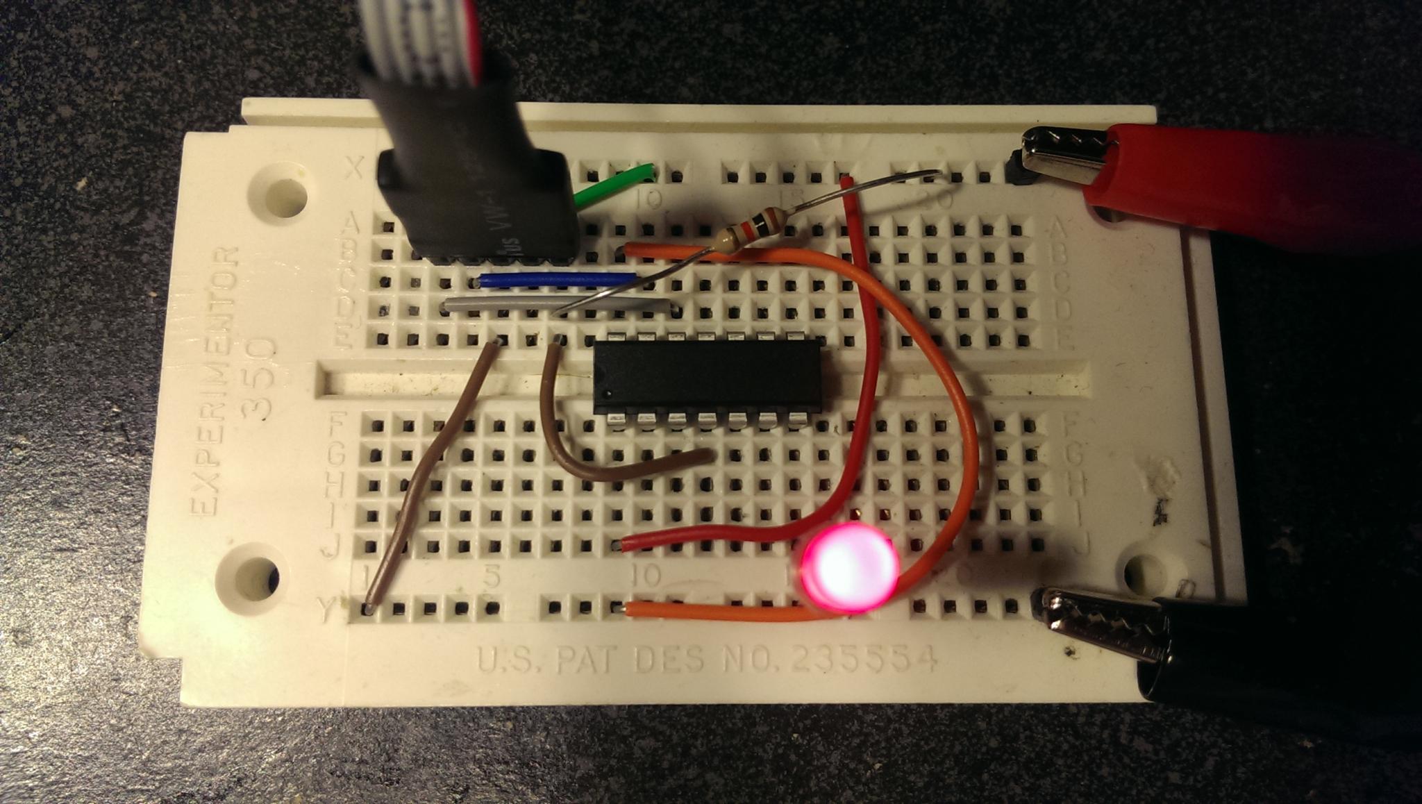
The end result is a flashing LED every 500 milliseconds.
Now, you know enough to dangerous.

3 Comments